Tuesday, September 8, 2015

A Basic hydrographic survey

Library

Survey equipment used in hydrographic surveys is described in this section. Survey equipment is continuously being developed and updated, however, the basic composition does not change. Survey equipment consists mainly of a sounding system and a positioning system. 

Sounding systems

Echo-sounders

An echo-sounder is the most common sounding system used in hydrographic surveying, and it is used to measure the depth to the seafloor by using the properties of acoustic waves. The principle of echo-sounders is basic – by measuring the two-way travel time between the acoustic waves transmitted on sea surface and those reflected at seafloor. The acoustic wave propagates through sea water at approximately 1,500 m/s. For example, in the case of a measured two-way travel time being 4 seconds, the water depth is computed as 1,500 × 4 ÷ 2 = 3,000 m.
Echo-sounders are classified into two types, Single-beam Echosounder (SBES) and Multibeam Echosounder (MBES). The names of ‘single’ and ‘multi’ stem from the number of depth points measurements collected at the same time.
Library Picture by Takafumi Hashimoto.

Single-beam Echosounders (SBES)
SBES systems were developed about 80 years ago and have substantially contributed to important primary oceanographic discoveries and developments. SBES are still commonly used in hydrographic surveying. A SBES can measure only one point per acoustic echo wave (echo) emitted. The specifications of SBES are defined by beam angle and frequency of transmitted acoustic wave from the transducer. The transducer of an active sonar is able to emit and receive acoustic waves. The beam angle relates to the area the beam ensonifies at the sea floor. The frequency of acoustic wave used is related to the measurable depth, because higher frequency acoustic waves attenuate faster in the propagation process through the water column. The common SBES used in hydrographic surveys in shallow-water areas have beam angles of up to 10° with a relative high frequency echo, whereas deep water systems generally have an approximate 20° beam angle with relative low frequency echo.

Multibeam Echosounder (MBES)
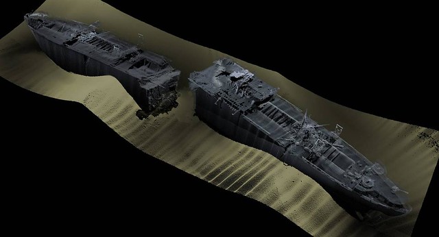
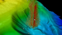
MBES systems were developed about 50 years ago, and are also commonly used in hydrographic surveys together with SBES. The basic concept of measuring of depth by MBES is the same as for SBES, but a MBES is capable of measuring many points of depth over a wide swath area at the same time. This is very important point in hydrographic surveys, particularly from the viewpoint of time and cost saving, due to the high coverage ratio of surveying. An along track line of single depth measurements can be obtained by SBES surveys, whereas a plane of depths can be collected by MBES surveys. The specifications of MBES are characterized by swath angles, in addition to the beam angle, and frequency of the acoustic wave. The swath angle is equal to the number of single beams times the beam number, giving the width of ensonified area perpendicular to the track line. In general, the specifications of common new MBES have swath angles of 150 degrees with less than a 1 degree beam angle. 

Satellite Altimetry

Information about ocean bathymetry can be estimated by satellite altimetry. The principle of the satellite-altimetry bathymetry is to accurately measure the distance between the satellite and sea-surface height, where this sea-surface height is argued to approximately represent the geoid surface. If the height of the satellite is known in the geocentric coordinate system, then the sea-surface height, which is the distance between earth ellipsoid and sea surface, can be computed. Geoid height therefore give the gravitational anomaly, which is mostly produced by seafloor features in oceanic areas. One of the merits of using satellite altimetry is the huge coverage on a whole ocean scale. The world bathymetric map published by GEBCO is based on ship survey depth data combined with interpolated satellite altimetry data. 

Airborne Lidar bathymetry (ALB)

ALB is able to measure water depth by aircraft equipped with laser ranging system instead of survey vessel with systems that produce acoustic waves. The ALB generally transmits two types of lasers, a green laser and an infrared laser. The green laser can measure the distance between the aircraft and the sea bottom, while the infrared laser, which is absorbed by water, measures the distance between the aircraft and sea surface. The merits of ALB is that they are quick and safer surveys in shallow-water areas, when compared with surveying by vessels. Shallow-water areas measured using traditional echo-sounder methods take much longer, because the shallower the water, the smaller the ensonified area becomes and as a result it takes a long time to survey. In addition, shallow water increases the risk of stranding of survey vessels, while these problems don't arise for ALB systems. However, ALB is limited to the very shallow water (about up to 50 m) and is unable to measure depths in deeper water area due to decay of laser energy in the water column. 

Positioning systems

Library Picture by Takafumi Hashimoto.

Position determination is also an important part of hydrographic surveys because making a map or nautical chart requires a connection between the measured depth with the accurately known position. In the early days, the position of a ship for navigational purposes was determined by geometric computation of star positions or by certain known targets on land, so called astronavigation and pilotage navigation. However, these ways of position determination include large errors and have a lot of visibility limitations (such as distance and weather condition). Radio navigation, which uses radio waves, was developed in order to overcome these limitations. In radio navigation, the ship's position is determined by solving the geometric positional relationship between the ship and multiple known ground-base stations, that are computed by the arrival times of the radio waves transmitted from these stations. The positional precision, for example, of Loran-C, which is one of radio navigation systems that was commonly used for navigation in the past was within 30 to 300 m.
Today, Global Positioning Systems (GPS) are mostly used for determining a ship’s positions. The GPS system was developed by the U.S. Defense Department in the 1970s. The principle behind GPS positioning is similar to that of radio navigation. GPS satellites are equipped with very accurate clocks and the signal transmitter, and GPS receivers on ship can receive the signal transmitted from GPS satellites. The distance between a GPS satellite and a receiver can be determine by timing the difference between transmitted and receive times. The receiver position can also be determined by computing the geometric relation among the multiple GPS satellites and the receiver at the same time. GPS positioning has few restriction, and it can be used anywhere, even in the ocean very far from land. The positional precision of GPS is approximately within 10 m. If differential GPS (DGPS) signal is available, then the positional accuracy can be accomplished within a cm order at best. In the case of DGPS, the GPS positioning is corrected by the differences between the true geodetic position and the GPS-measured position at a known reference station that is located on the nearby land at some fixed point.
Library
Picture by Takafumi Hashimoto.

References:
  1. http://www.gebco.net/general_interest/faq/, (June 15, 2013)
  2. http://oceanexplorer.noaa.gov/history/electronic/electronic.html, (June 15, 2013)
  3. http://oceanexplorer.noaa.gov/history/electronic/electronic.html, (June 15, 2013)
  4. http://www.hydro-international.com/files/productsurvey_v_pdfdocument_30.pdf, (June 15, 2013)
  5. http://www.hydro-international.com/files/productsurvey_v_pdfdocument_33.pdf, (June 15, 2013)
  6. E.P. Baltsavias, 1998, Airborne laser scanning: existing systems and firms and other, ISPRS Journal of Photogrammetry & Remote Sensing, v. 5, p. 164–198
  7. http://en.wikipedia.org/wiki/Navigation, (June 15, 2013)
More learning
  1. http://www.hydro-international.com/productsurvey/index.php, (June 15, 2013)
  2. W.H.F. Smith and D.T. Sandwell, 1997, Global Sea Floor Topography from Satellite Altimetry and Ship Depth Soundings, Science, v. 277, p. 26

Sunday, July 12, 2015

Fugro Americas completes first job

Written by   Thursday, 09 July 2015 09:19
Rate this item
(0 votes)
On 11 June 2015, Fugro’s premier geophysical survey vessel, the Fugro Americas, successfully completed a data-collection project for a geochemical coring campaign in the Caribbean. The project marks the maiden voyage of the new-build vessel, reports Fugro.
Fugro accepted delivery of the new shallow-draft survey vessel in March. The vessel was custom designed to Fugro’s specifications and fitted with the latest geophysical survey equipment, including some of the most advanced instrumentation in the field, according to Fugro.
The Fugro Americas was designed for optimized work in the Gulf of Mexico (GOM), but is capable for other regions. The SOLAS-class vessel is 59m long with a beam of 41m and gross tonnage of 490. Its operating range is 8000 nautical miles at a cruising speed of 10 knots (max 12 knots).
The vessel can acquire high-resolution geophysical and light geotechnical surveys in water depths of up to 4500m.Fugro Americas is built to operate Fugro’s new 4500m-rated Hugin 1000 autonomous underwater vehicle (AUV), Echo Surveyor VII, which was delivered in December 2014. Specialist equipment on the new survey vessel includes a dynamic positioning system, state-of-the-art survey systems (2D seismic multi-channel) and a deepwater EM302 multibeam echosounder to be used for gas seep surveys. It was built by Thoma-Sea Marine Constructors in Louisiana.
The Fugro Americas was mobilized for the new project immediately following the vessel’s departure from the construction shipyard in in April. The integrated project was comprised of 141 piston cores and 7 heat flow measurements that yielded more than 1500 biological and geochemical samples.
The vessel is the result of Fugro’s announcement in 2014 that it would expand its survey fleet in the GOM.
“We already operate three AUVs in the GOM – one Hugin (Echo Surveyor II), and two Bluefin (Echo Mapper), and our new multi-purpose Fugro Americas vessel enables us to have three vessels capable of operating AUVs in the Americas," says Melissa Jeansonne, vice president for Fugro GeoServices.
Jim Grady, asset manager for Fugro GeoServices says, “At 193ft, she is bigger and faster than our current vessels in the GOM, has more berths as part of our purpose-built design, and is both quiet and fuel efficient. SOLAS-classed, she is capable of undertaking seismic, conventional, AUV and geotechnical surveys, thus providing the advantage of just one mobilization.”
Image: Fugro Americas / Fugro

Wednesday, February 25, 2015

Oceaneering to Acquire C & C Technologies

Oceaneering  Expands Service Line Capabilities and Enhances Underwater Service Offerings


February 2, 2015 – Houston, Texas – Oceaneering International, Inc. (NYSE:OII) announced that it has entered into a definitive agreement to acquire C & C Technologies, Inc. (C&C), a privately-held global provider of survey services, for approximately $230 million in cash.

Headquartered in Lafayette, Louisiana, C&C is a leading provider of ocean-bottom mapping services in deepwater utilizing customized autonomous underwater vehicles and provides marine construction surveys for both surface and subsea assets, as well as satellite-based positioning services for drilling rigs and seismic and construction vessels. C&C also provides land and near-shore survey services along the U.S. Gulf Coast and in Mexico, and performs shallow water conventional geophysical surveys in the U.S. Gulf of Mexico.

The transaction is anticipated to be completed in early April 2015, subject to customary closing conditions. In the 12 months following closing, Oceaneering expects the acquired business to generate $20 million to $30 million of EBITDA, before integration costs, and to be accretive to earnings. Oceaneering plans to include C&C’s financial results in its Subsea Projects segment.

M. Kevin McEvoy, President and Chief Executive Officer, stated, “We are pleased to have entered into an agreement to acquire C&C, as we believe this transaction is a unique opportunity to strategically expand our service line capabilities and underwater service offerings. C&C’s services are used in all of the major phases of an offshore field life cycle, particularly in exploration and development, and are highly complementary with Oceaneering’s products, services, capabilities and areas of expertise. Benefits we anticipate include: increased use of our remotely operated vehicles and vessels to support survey services; enhancement of our ability to secure subsea asset integrity work on pipelines, including x-ray and ultrasonic inspections, which could pull through additional demand for tooling and pipeline repair systems; and increased demand for our video and data solutions service.

“We are looking forward to the contributions that the more than 550 C&C personnel will make to our operations and growth. In addition, we expect to achieve cost savings and revenue synergies as we integrate C&C’s operations and bring its services to new markets by leveraging our extensive international footprint.”

Oceaneering also announced that Thomas Chance, Co-founder and President of C&C, has agreed to remain with the company for at least a year, to facilitate a smooth transition. He will assist in assimilating C&C’s business into Oceaneering and developing a plan for growth that takes advantage of Oceaneering’s existing service line capabilities to provide integrated solutions for customers.

Oceaneering expects to issue 2014 year-end earnings on February 11, 2015 and will update its overall 2015 outlook at that time.

In accordance with the Safe Harbor provisions of the Private Securities Litigation Reform Act of 1995, Oceaneering International, Inc. cautions that statements in this press release which are forward-looking involve risks and uncertainties that may impact Oceaneering’s actual results. The forward-looking statements in this press release concern Oceaneering’s: expected acquisition price; anticipated timing for the closing; expected EBITDA generated from the acquired business; expectation that the acquisition will be accretive to earnings; plan to include C&C financial results in Subsea Projects segment; belief the acquisition will expand service line capabilities and underwater service offerings; belief that C&C services are complementary with Oceaneering’s products, services, capabilities and areas of expertise; list of anticipated benefits; expected contributions from C&C personnel; expected cost savings and revenue synergies as operations are integrated and services are introduced to new markets; expectation that Thomas Chance will remain with the company for at least a year and assist in assimilating C&C’s business and developing a plan for growth; and intent to update its 2015 outlook in its 2014 year-end earnings release to be issued in mid-February 2015. Although Oceaneering’s management believes that the expectations reflected in these forward-looking statements are reasonable, Oceaneering can give no assurance that the expectations will prove to have been correct. The forward-looking statements are made based on various underlying assumptions and are subject to numerous uncertainties and risks, including, without limitation, contract termination and risks related to the satisfaction of the various closing conditions for the acquisition transaction. If one or more of these risks materialize, or if underlying assumptions prove incorrect, actual results may vary materially from those expected. These and other risks are more fully described in Oceaneering’s latest annual report on Form 10-K and its other periodic filings with the Securities and Exchange Commission. Oceaneering undertakes no obligation to update or revise any forward-looking statements to reflect new information or the occurrence of unanticipated events or otherwise, except as required by applicable law.

We define EBITDA as net income plus provision for income taxes, interest expense, net, and depreciation and amortization. EBITDA is a non-GAAP financial measure. We have included EBITDA disclosures in this press release because EBITDA is widely used by investors for valuation and comparing our financial performance with the performance of other companies in our industry. Our presentation of EBITDA may not be comparable to similarly titled measures other companies report. Non-GAAP financial measures should be viewed in addition to and not as an alternative for our reported operating results or cash flow from operations or any other measure of performance as determined in accordance with GAAP.

Oceaneering is a global provider of engineered services and products, primarily to the offshore oil and gas industry, with a focus on deepwater applications. Through the use of its applied technology expertise, Oceaneering also serves the defense, entertainment, and aerospace industries.

For further information, please contact Jack Jurkoshek, Director Investor Relations, Oceaneering International, Inc., 713-329-4670, investorrelations@oceaneering.com.

PR 1208

View/Download: PDF File

Saturday, October 25, 2014

Maritime Journal - Hugin finding worldwide orders

Maritime Journal - Hugin finding worldwide orders

Teledyne Broadens Portfolio with Oceanscience Acquisition

Teledyne Technologies Incorporated has announced that a subsidiary has acquired the business and substantially all assets of The Oceanscience Group Ltd. Based in Carlsbad, California, Oceanscience designs and manufactures marine sensor platforms and unmanned surface vehicles. Terms of the transaction were not disclosed.
Oceanscience is a leader in the development of oceanographic and hydrographic deployment equipment designed to save survey time and improve data quality. Major products include remotely-controlled and tethered instrumentation deployment vehicles used for current measurement, seafloor mapping and analysis of physical parameters such as salinity.
“Through the acquisition of Oceanscience, as well as the recent investment in Ocean Aero and the pending acquisition of Bolt Technology and its Seabotix division, we will have significantly broadened Teledyne’s portfolio of remotely-operated and autonomous marine systems,” said Robert Mehrabian, chairman, president, and CEO of Teledyne. “Specifically, Oceanscience adds unmanned surface vessels to our line of profiling floats, battery-powered autonomous underwater vehicles and market-leading autonomous gliding vehicles.”
Ron George, president of Oceanscience, said, “After working closely with Teledyne for 16 years, the entire Oceanscience team is excited about the opportunity to continue developing innovative, industry-leading products and to accelerate the company’s growth as part of Teledyne.”
Claiborne Advisors, Inc., who represents founder-owners and companies in transactions in Southern California and New Mexico, acted as financial advisor to Oceanscience.
About Teledyne Technologies
Teledyne Technologies is a leading provider of sophisticated instrumentation, digital imaging products and software, aerospace and defense electronics, and engineered systems. Teledyne Technologies’ operations are primarily located in the United States, Canada, the United Kingdom, and Western, and Northern Europe. For more information, visit www.teledyne.com.

Saturday, January 12, 2013

Esri and QPS Strengthen Partnership to Develop Ocean Science Tools


Esri and QPS Strengthen Partnership to Develop Ocean Science Tools

Quality Positioning Services (QPS) has signed an original equipment manufacturer (OEM) agreement with Esri, the world leader in GIS technology. The agreement enables QPS to bundle its QINSy and Fledermaus products with Esri software and provide a complete hydrographic survey, data management, and charting solution.
“This worldwide OEM agreement with Esri allows us to provide our clients with seamless access to comprehensive GIS software within a multifunctional, integrated survey software suite,” said Lindsay Gee, QPS product manager.
QPS will incorporate two of Esri’s ArcGIS applications into an end-to-end hydrographic package, QINSy Premium. One application is ArcGIS for Maritime: Bathymetry, which indexes, searches, and models bathymetric data. The other is ArcGIS for Maritime: Charting, which makes it possible to capture, maintain, and manage nautical data in a centralized database. The package will also include QINSy hydrographic data acquisition and processing software as well as Fledermaus 3D visualization and data analysis technology.
“Esri’s partnership with QPS demonstrates our commitment to support all aspects of the marine community’s work at sea, on coastal areas, and in inland waters,” said Rafael Ponce, Esri director of maritime business development.
The QINSy Premium solution will provide hydrographers, marine scientists, planners, and engineers with a seamless integrated solution for robust marine survey data collection, efficient processing, and state-of-the-art storage and distribution of data products. For more information on the QINSy Premium bundles, contact the QPS project manager at fminfo@qps.nl or fminfo@qps-us.com.
For more information about GIS for ocean science, visit esri.com/oceans.
Source: Esri press release, November 26, 2012
This entry was posted in 3D GISOceans & Maritime and tagged ,. Bookmark the permalink.

Sunday, January 6, 2013

AmeriSurv.com - Oceanscience Hydrographic Survey Z-Boat—Visible from Space

The American Surveyor Sunday, Jan. 6, 2012   

Oceanscience Hydrographic Survey Z-Boat—Visible from SpacePrintE-mail
Written by Oceanscience   
Saturday, 15 December 2012
In a freak coincidence, surveyors from Select Energy Services, San Antonio, TX were surprised to see one of their remotely operated hydrographic survey vehicle’s activities photographed and incorporated onto Google Earth! Water Sourcing Manager Justin Duke was preparing to embark on a hydrographic survey of a water 
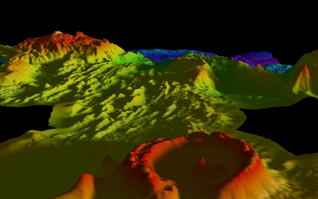
holding pond for a natural gas fracturing operation in Texas when he was very surprised by what he found.  Justin and his team use the Oceanscience (San Diego, CA) remotely-operated Z-Boat 1800 to conduct holding pond volume surveys that are crucial to effectively manage industrial process water inventories.

Prior to leaving for the survey site, the Select Energy Services process calls for the Google Earth map of the pit to be uploaded to the acquisition software to provide a background image for the survey plan and to offer clients a familiar perspective when viewing the final survey product. When the lat/long was inserted and the Google Earth image came into focus, a small yellow dot visible in the middle of the frac pit appeared and seemed to have a wake behind it. On increasing the zoom, Justin was amazed to see his Z-Boat clearly in the satellite image – and he had not even started the survey! The photograph used on Google Earth was taken exactly when Justin was at the pit for the previous time it was surveyed – for about an hour a few months before. After conducting the survey as usual, the bathymetric map image was generated for the client although this time with the added benefit of a freak photographic coincidence included at no extra charge! Using an average age of Google Earth imagery of around three years, the approximate odds of this photograph existing are about 1 in 25,000.

The Z-Boat incorporates a single beam echo sounder, GPS and telemetry system to allow fast bathymetric surveys without any requirement to launch a manned boat onto the water. For these relatively small surveys, the Z-Boat is ideal as several pits can be surveyed in each day with just a single surveyor on the job.

USGS Data Conference
The Oceanscience Z-Boat 1800 in action at the USGS Data Conference, September 2012. Portland, OR. Single beam depth sounder installed on the latest high specification remotely operated boat. Ideal for shallow water hydrographic surveys:


For more information on The Oceanscience Group visit www.oceanscience.com.


Tuesday, July 26, 2011

Discovering mammoth undersea mountains

Using multibeam sonar, Scripps R/V Melville is charting giant undersea mountains. (PhysOrg.com) -- In the latest evidence of the vastness remaining to be explored in the world’s oceans, scientists aboard Scripps Institution of Oceanography at UC San Diego’s research vessel Melville are mapping a series of colossal and previously uncharted undersea mountains in remote areas of the South Atlantic Ocean. With the largest seamount rising more than 14,700 feet from the seafloor—higher than California’s Mount Whitney, the tallest mountain in the contiguous United States—the mountains had been known from satellite data but never before charted at sea. Because of the exploratory nature of the ship’s navigation, R/V Melville Captain Chris Curl and geophysicist J.J. Becker, who received his Ph.D. from Scripps in 2008, are working side-by-side to navigate over the gigantic mountains, the largest of which spans some 140 kilometers (87 miles) across (the approximate distance from San Diego to Long Beach, Calif.) “These particular seamounts are so steep that it was nerve-wracking to go from 3,000 meters (9,840 feet) of water to less than 500 meters (1,640 feet) in 15 or 20 minutes!” said Becker. David Sandwell, a Scripps professor of geophysics, has been providing guidance to the ship from his office on the Scripps campus as the vessel transits from South Africa to Chile. The researchers are employing a new survey tool based on Google Earth software called “Seamount Discovery Tool” to aid in the exploration. “There are still 4,000-meter-tall undersea mountains that have never been charted by anyone,” said Sandwell, of Scripps’ Cecil H. and Ida M. Green Institute of Geophysics and Planetary Physics. “These are really huge seamounts that are somewhat known from satellite altimetry, so the ship data confirm their size and provide accurate measurements.” The seamounts, mapped by Melville’s multibeam sonar, are located in the South Atlantic Ocean approximately 1,200 miles southwest of Cape Town, South Africa. (latitude 42°S, longitude 00°E). Prior to Melville’s departure, Sandwell provided a proposed trackline where the ship might explore uncharted undersea features. Foul weather in the South Atlantic (persistent in the Southern Ocean) required the scientists to modify their exploration path almost immediately after leaving port. The alternate track, however, has revealed the presence of surprising numbers of large, flat-topped underwater mountains with extremely steep sides, called “guyots.” “This is a great example of how serendipity and skill are involved in successful exploration and discovery,” said Bruce Appelgate, associate director for Ship Operations and Marine Technical Support at Scripps. “Dave Sandwell used the satellite data to create a great precruise plan, but the seas forced us to abandon that for a different path. Good oceanographers that they are, he and J.J. Becker were ready with contingency plans that have yielded spectacular results.” Seamounts, especially massive seamounts like these, are important for many reasons, said Appelgate. The chemistry of the volcanic rock they are made from provides information about the underlying mantle where the seamounts formed. “They are so big they actually deform the lithosphere they sit on, and they have a profound effect on the physical oceanography and biological ecosystems around them,” said Appelgate. “Satellite altimetry has detected about 13,000 seamounts, but the total number of seamounts taller than one kilometer probably exceeds 100,000. So clearly these are important, and you need ships like Melville, and scientists like Sandwell and Becker, to go find them.” Becker and Sandwell noted that such discoveries can be made by diverting from the traditional “Great Circle” route of sea transit. The Great Circle is the shortest distance between two ports but significant discoveries can be made by increasing the path by just three percent. Considering uncertainties in weather, a longer path can save time and fuel so it is important for the ship’s captain to be involved in mapping decisions. Scripps’ R/V Melville is currently being repositioned from the South Atlantic to the South Pacific in order to support major research programs funded by the National Science Foundation. Scripps’ policy is to use every opportunity at sea to collect meaningful data, so rather than simply transit across the ocean, Scripps provided funding through its UC Ship Funds Program to enable a diverse group of scientists to join the research vessel in Cape Town and acquire data. The cruise is led by Scripps Chief Scientist Robert Frouin, who along with his research team is making observations about the physics of the air-sea interface in areas of extreme wind. These data will be used to improve scientists’ ability to interpret data collected globally by satellites. Other Scripps scientists on board are deploying autonomous ocean drifters and building new software tools for shipboard data processing. Melville will continue to cross the South Atlantic, pass through the Strait of Magellan and cruise up the west coast of Chile to its destination at Valparaiso, Chile. From there, Melville will continue its expedition of discovery by resuming an investigation of the deformation of the ocean floor caused by the magnitude-8.8 Chile earthquake of February 2010. Last year the ship performed the first-ever detailed seafloor mapping of a major subduction zone earthquake as part of the Scripps rapid scientific response to the Chilean earthquake. The additional data will shed new light on how the crust responds in the wake of giant earthquakes. Owned by the U.S. Navy and operated by Scripps Oceanography, the 279-foot R/V Melville is a global-class ship that conducts long-duration science missions. Last year, the U.S. Office of Naval Research selected Scripps as the operator of a new Ocean Class scientific research vessel, which is currently being designed with input from Scripps oceanographers. The U.S. Navy is providing more than $88 million to construct the vessel, which is anticipated to be ready for Scripps to operate by 2015. Provided by University of California - San Diego

Tuesday, May 10, 2011

Multibeam Rendering of the SS Richard Montgomery,


photo

The SS Richard Montgomery, off Sheerness in the Thames Estuary. Courtesy MCA

This WW2 Liberty ship was transporting munitions when it ran aground and broke its back in 1944. At the time the bombs were transported across the atlantic with the fuses attached. Contemporary salvage emptied the stern half but the forward section still contains many thousands of tones of high explosives.

Saturday, December 19, 2009

'Fried Egg' may be impact crater

By Jonathan Amos
Science correspondent, BBC News, San Francisco

Fried Egg: Vertical exageration factor is 2 (EMEPC)
The Egg and its companion obtained by multibeam echosounder bathymetry

Portuguese scientists have found a depression on the Atlantic Ocean floor they think may be an impact crater.

The roughly circular, 6km-wide hollow has a broad central dome and has been dubbed the "Fried Egg" because of its distinctive shape.

It was detected to the south of the Azores Islands during a survey to map the continental shelf.

If the Fried Egg was made by a space impactor, the collision probably took place within the past 17 million years.

This is the likely maximum age of the basaltic sea-floor rock which harbours the feature.

"To be sure, we need to take samples and make a profile of the sediment layers to determine if there really is a central uplift from an impact," explained Dr Frederico Dias from EMEPC (Task Group for the Extension of the Portuguese Continental Shelf).

"We need also to see all the signatures that are consistent with a high velocity impact, like glasses from melting and, of course, debris; and what are called shatter cones (shocked rocks)," he told BBC News.

Central peaks

Dr Dias described the putative impact feature here at the American Geophysical Union's (AGU) Fall Meeting, the world's largest annual gathering of Earth scientists.

The Fried Egg was first identified in data gathered by a 2008 multibeam echosounder hydrographic survey. A further cruise from September to November this year confirmed its presence.

It lies under 2km of water about 150km from the Azores archipelago.

The depressed ring sits roughly 110m below the surrounding ocean bottom, with the circular dome-shaped central uplift 3km in diameter and with a base-to-top height of some 300m.

Central peaks are often associated with meteorite impacts and form when the compressed crater floor rebounds. A peak is not definitive proof of an impact, however.

A volcanic origin for the Fried Egg seems unlikely because the Portuguese team has not been able to find any lava flows within the structure or on its surroundings.

Second crater

Interestingly, there is another - but much smaller - feature just 3-4km to the west of the egg.

"It's just by the side. If the Fried Egg is a crater, this could be a crater also," speculated Dr Dias.

Dr Dias and colleagues are examining gravity and magnetic data gathered during September's cruise. A third expedition to the area early next year will use a remotely operated vehicle (ROV) to try to retrieve samples from the ocean floor for analysis.

The Portuguese team detailed the currently available Fried Egg data on a poster at the AGU meeting. Other researchers who came to view the information were split on the impact theory, Dr Dias said.

"Even if it's not an impact crater it's still a very interesting feature," he told the BBC.

The EMEPC is working under the United Nations Convention on the Law of the Sea to establish the true extent of Portuguese territorial waters.

Wednesday, September 23, 2009

Fledermaus Technology Used in 1400 Meter Plume Discovery Off the Northern California Coast

Latest Technology from IVS 3D Used to Visualize Massive Plume. Read more about the discovery and view 3D video of the analysis.

Fledermaus Technology Used in 1400 Meter Plume Discovery Off the Northern California Coast Portsmouth, NH, September 23, 2009 --(PR.com)-- Fledermaus’ latest technology, mid-water visualization, has helped scientists to discover a 1400-meter plume off the northern California margin.

While on a cruise to test the new Kongsberg EM302 multibeam sonar in May 2009, the NOAA ship Okeanos Explorer, discovered a 1400 m high plume rising from the seafloor. The feature was noticed in the online display of the water-column data of the sonar, and further analyzed in the new Fledermaus mid-water visualization tool. The ship returned to the area in July, verified that the plume was still active, and detected a number of other plumes ranging in height from 700 to 1400 m in a 15 km area around the original discovery.

James V. Gardner and Mashkoor Malik (of The Center for Coastal & Ocean Mapping (CCOM) UNH and NOAA, respectively) participated on the cruise, and provided details of the discovery in the August 11, 2009 issue of EOS. Scientists cannot yet be certain of the composition, but they do feel reasonably certain that the plume is not a hydrothermal vent associated with the eastern section of the Mendocino Fracture Zone. The region is known for both subsurface and water-column gas; however, the reported gas plumes are confined to water depths of less than 200 meters. The discovery of this plume is significant because none has been reported in this area from such depths.

Moe Doucet, Chief System Architect for IVS 3D, noted. “IVS 3D jointly funded a project with a grant from the New Hampshire Innovation Research Center to support CCOM in the ongoing research and development of tools for the analysis and exploitation of multibeam sonar water column data. Until now, the users of these sonars had a limited view of the mid-water data in real-time, and limited capacity to store it, replay it, or run further analysis. The data also needs to be integrated with other sensor assets such as bathymetry, backscatter, sub-bottom, sea-floor characterizations and other assets so that a ‘complete’ picture of the marine environment under analysis can be realized. This discovery is just one example of the emerging uses of this type of data analysis.”

A video of the plume discovery is available on the IVS website, courtesy of CCOM and NOAA.

Interactive Visualization Systems (IVS 3D) was founded in 1995 as the developer of the Fledermaus 3D visualization and analysis software suite. Government, commercial and academic clients in all areas of ocean mapping use the software internationally.

The Fledermaus software stands apart in providing scientists and engineers with interactive and intuitive tools for processing, quality control, and analysis of multibeam sonar and related data. Its use significantly improves efficiencies in areas such as; nautical charting, geologic interpretation, the assessment of seabed habitats, planning routes for pipelines and cables, and the identification of geohazards during engineering development.

IVS 3D has offices in Canada, USA, and the UK, and a worldwide distribution network. For more information about the company and products, visit www.ivs3d.com.